Composites
Aeropanels
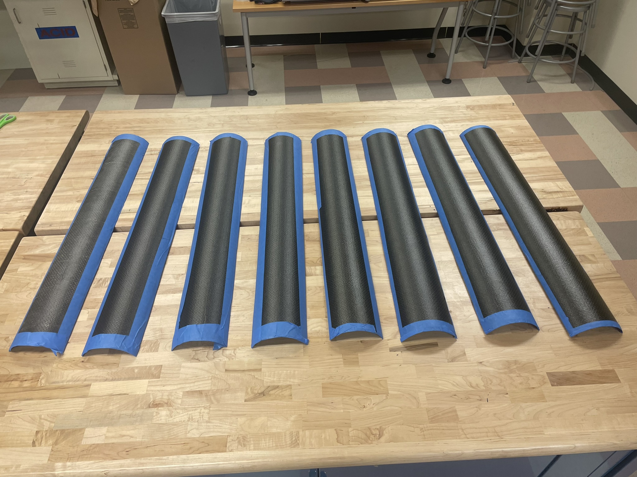
I co-developed the manufacturing process for Halya’s composite aeropanels: three-foot-long quarter-cylinder structures that enclose the rocket’s aluminum frame. This process began with creating a routed MDF positive mold and producing a fiberglass wet-layup mold that could withstand elevated-temperature curing. I then fabricated ASTM tensile and short-beam-shear coupons using varied layup methods to characterize material properties and identify the most effective manufacturing approach. After validating the process through testing and documentation, my team and I manufactured a full set of eight composite aeropanels for integration onto the vehicle.
- Completed aeropanels
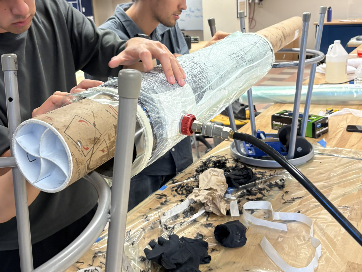
- Aeropanel layup in progress
- Finished aeropanels test-fitted on a replica strut
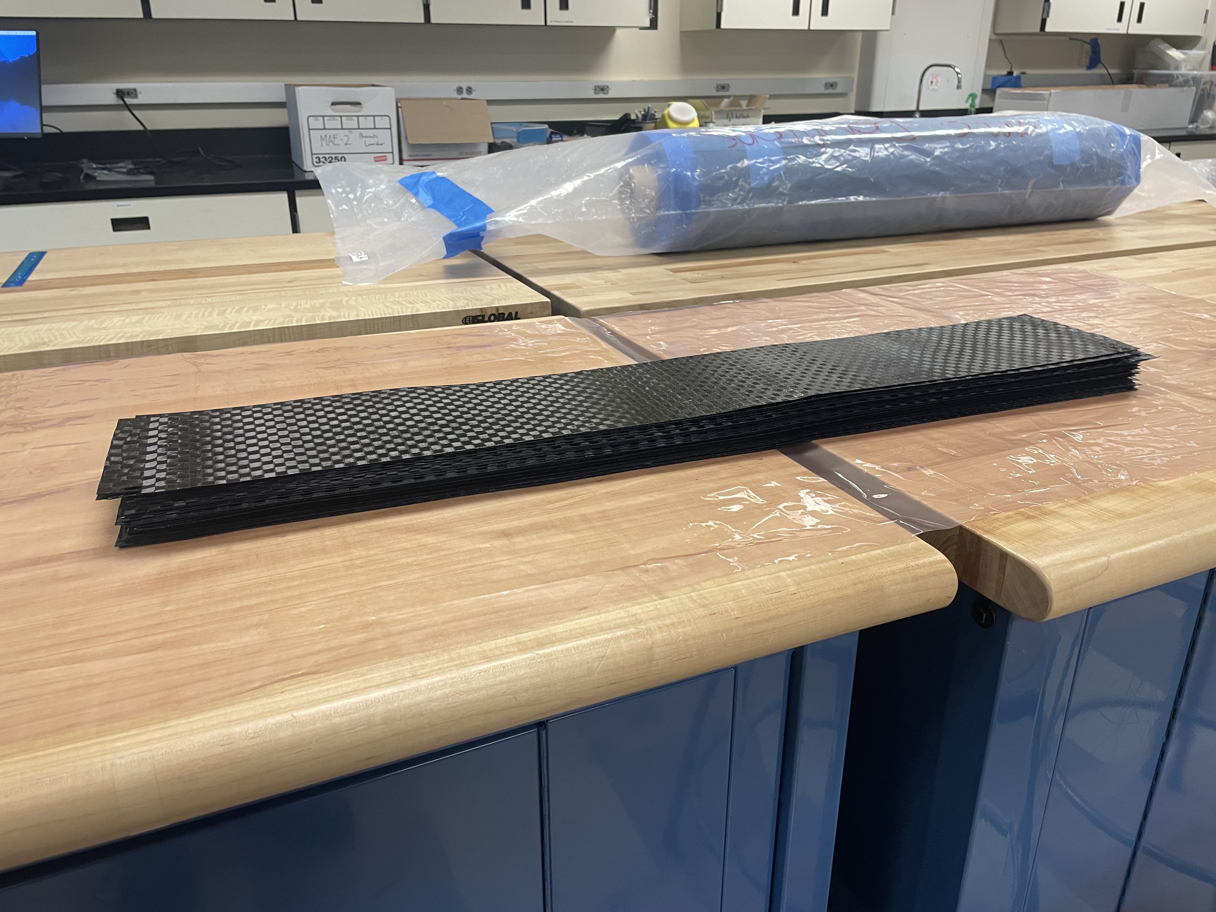
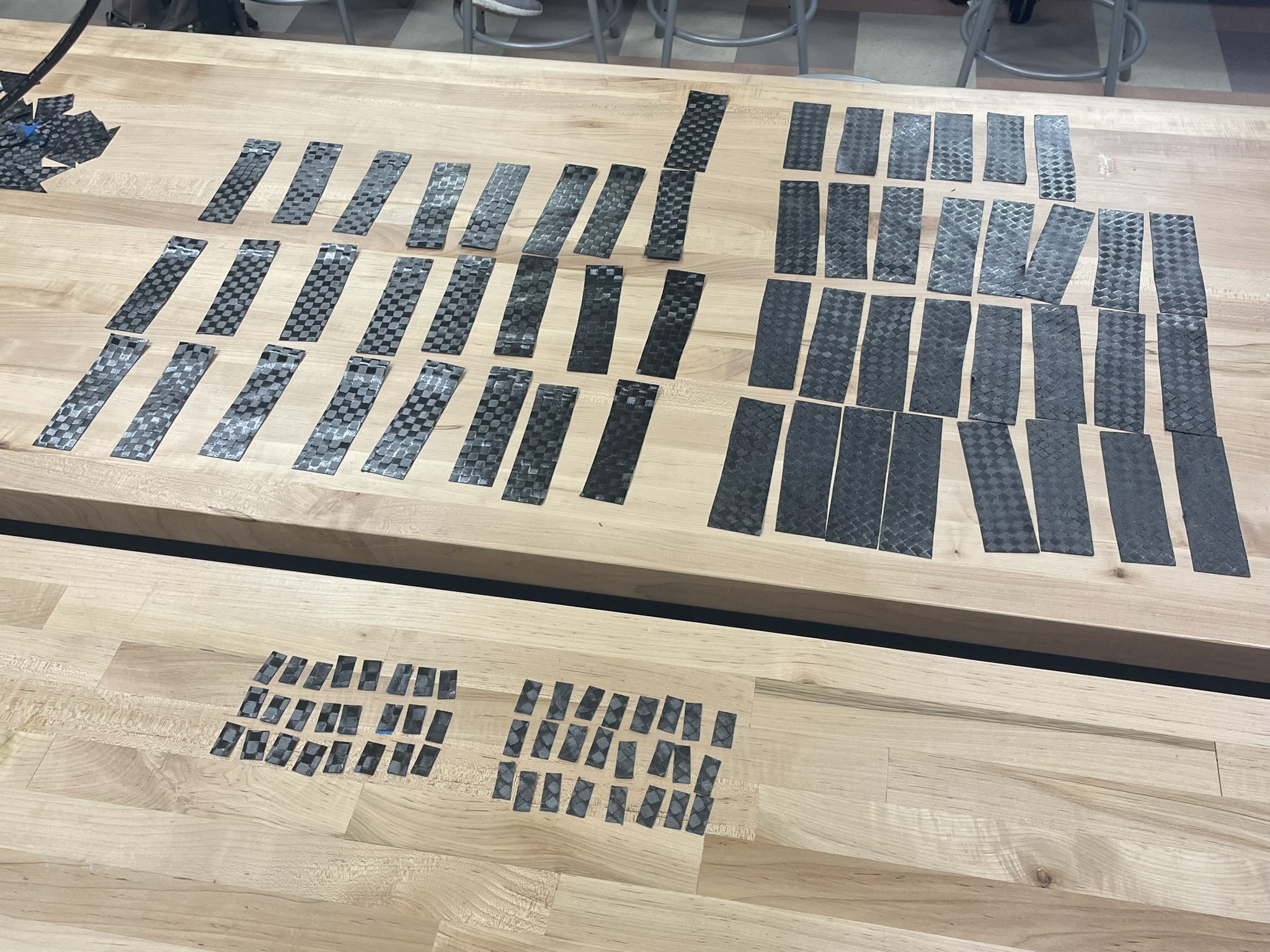
- Prepared plys
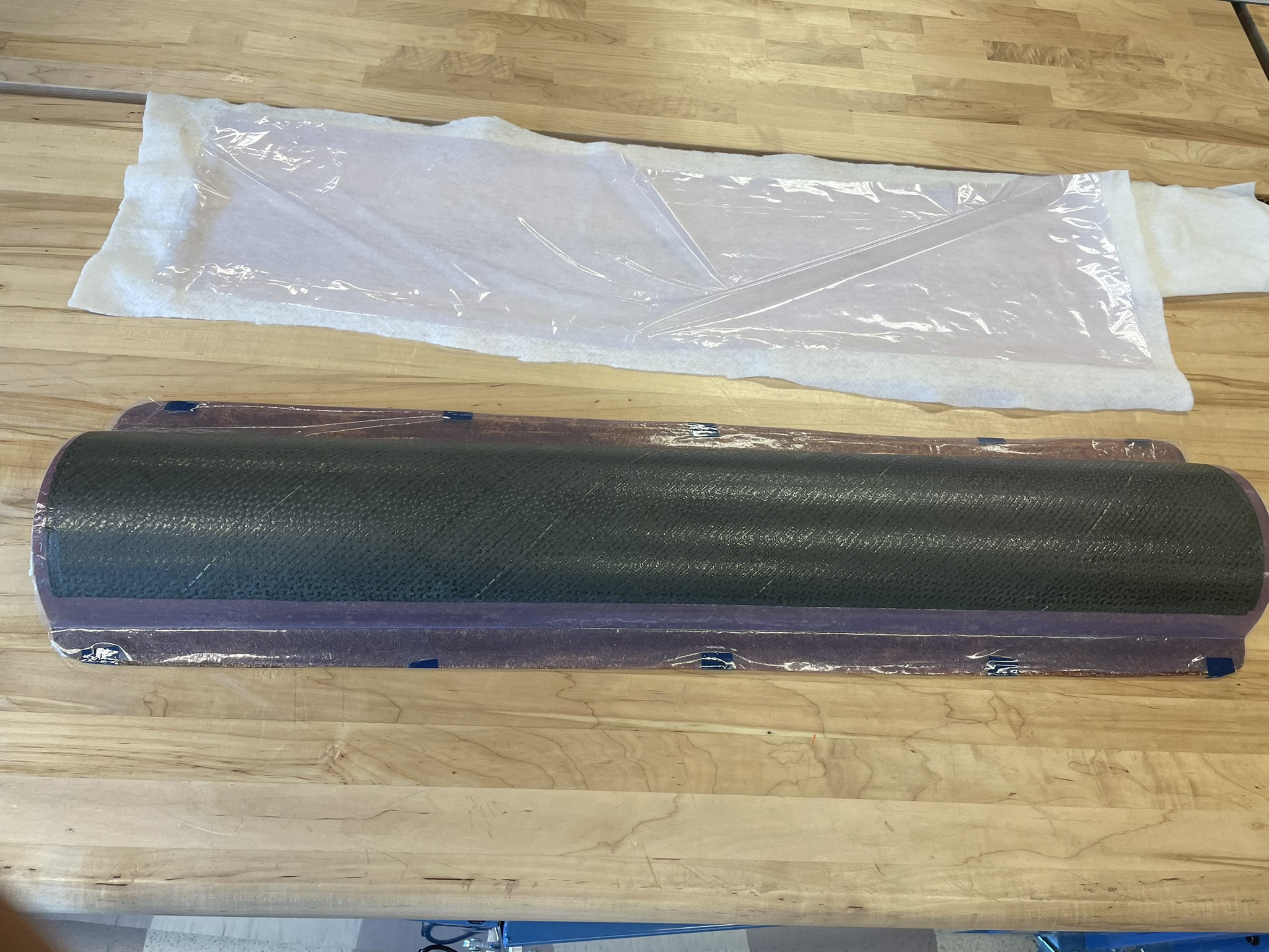
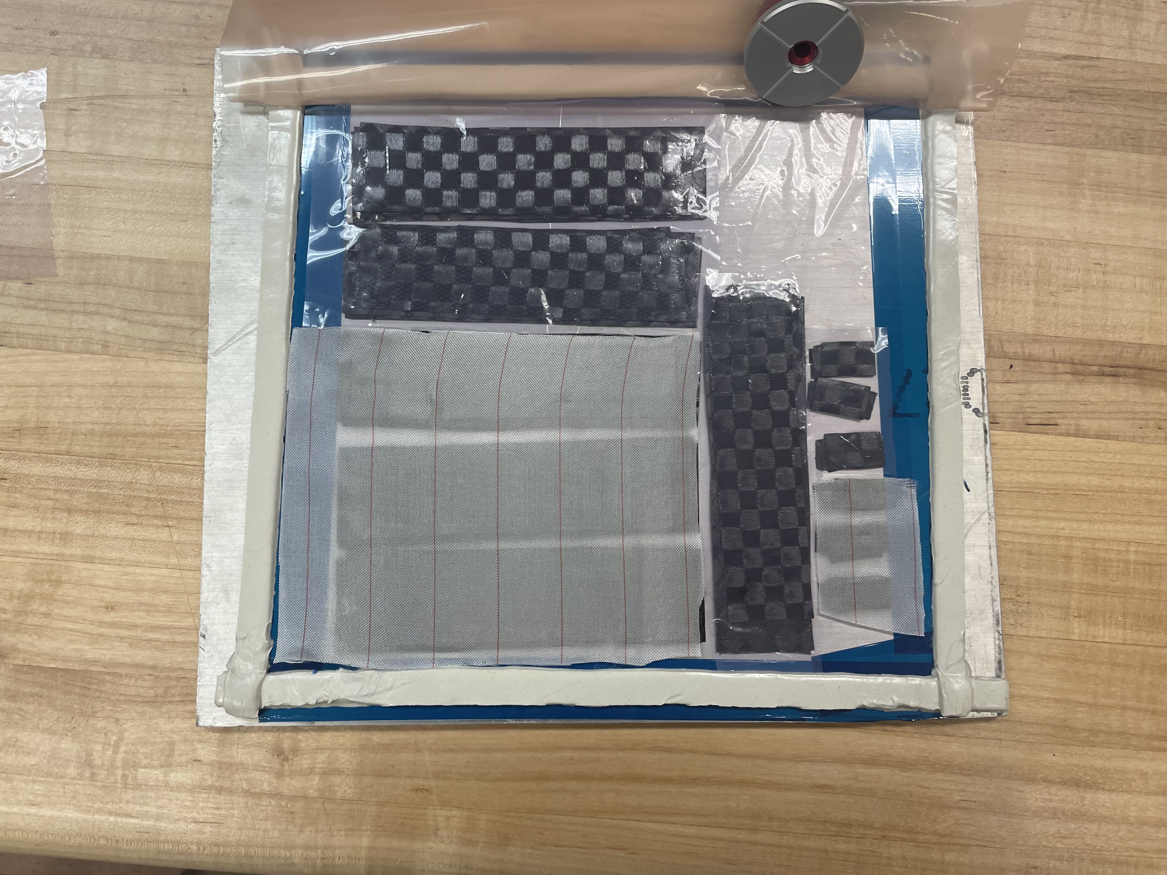
- Aeropanel layup in vacuum bag, prior to cure
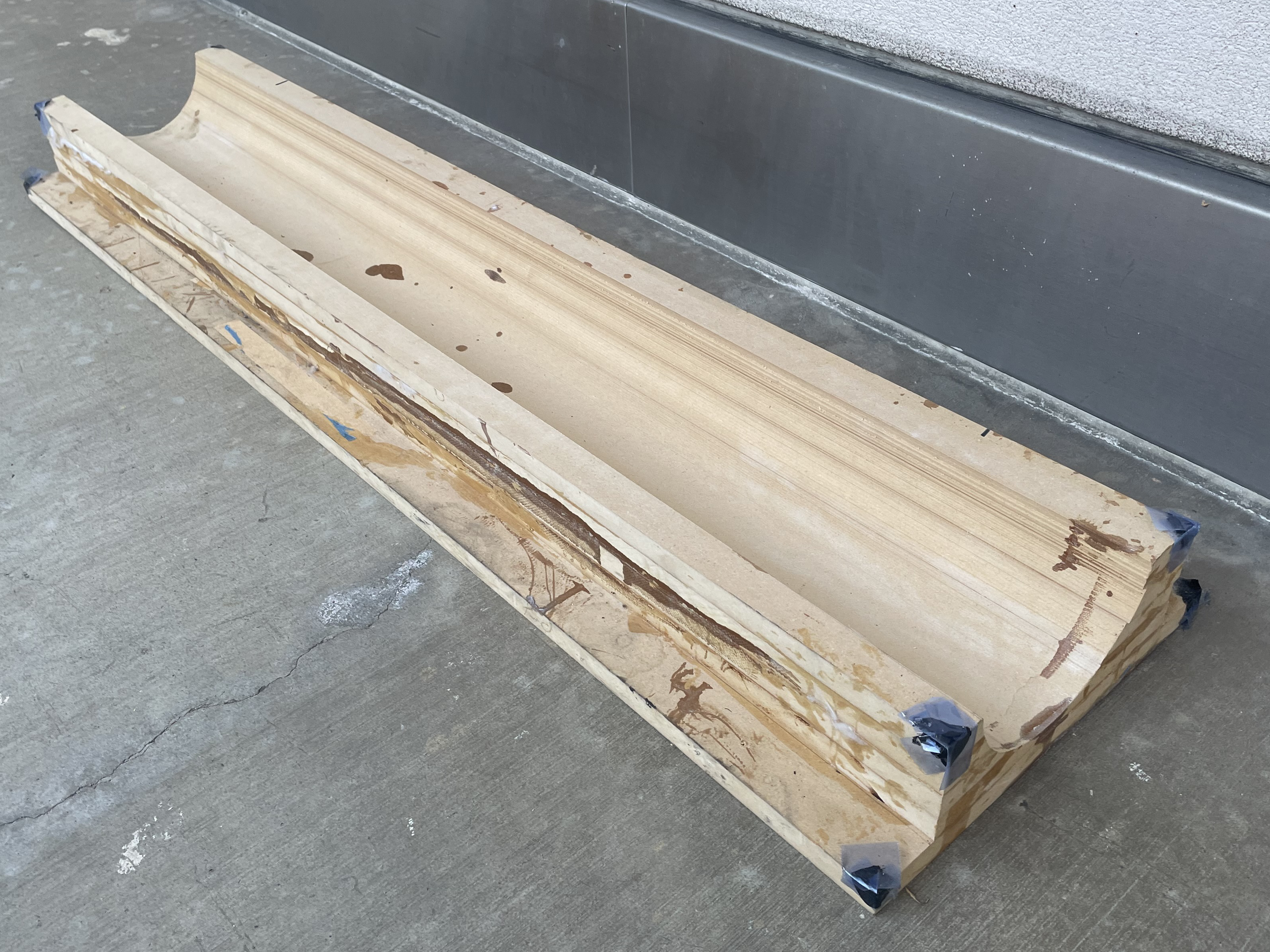
- MDF positive mold
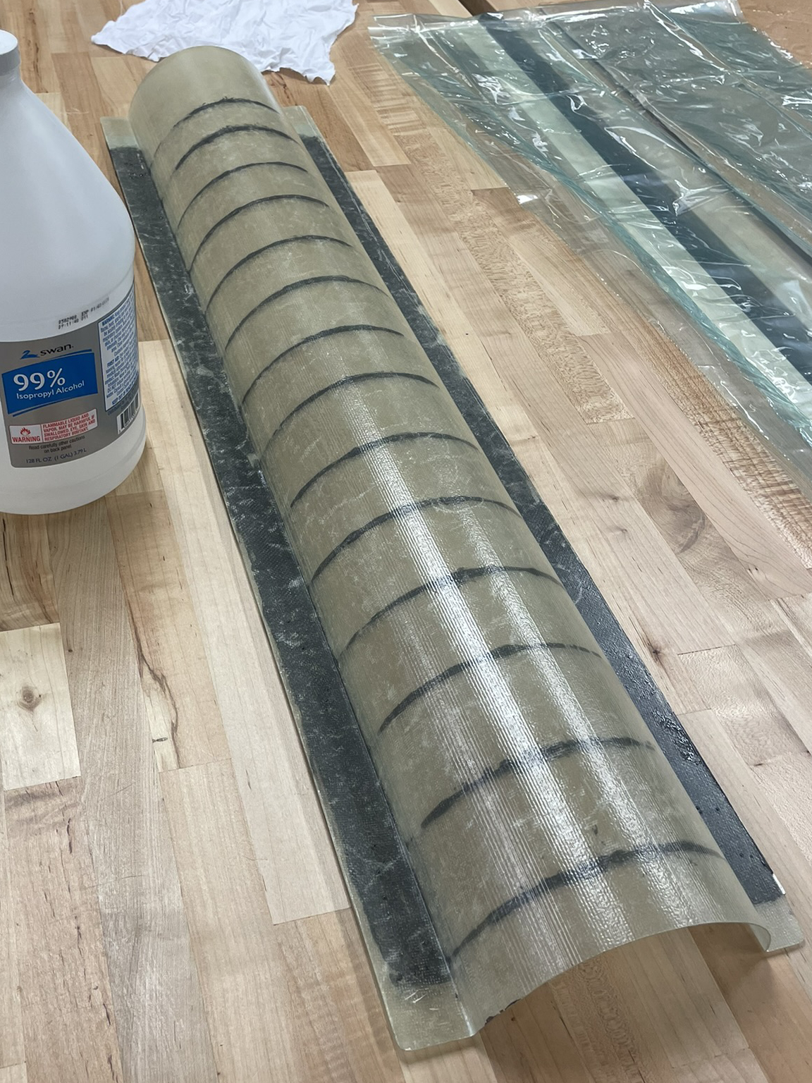
- First iteration fiberglass negative mold
- Second iteration fiberglass negative mold
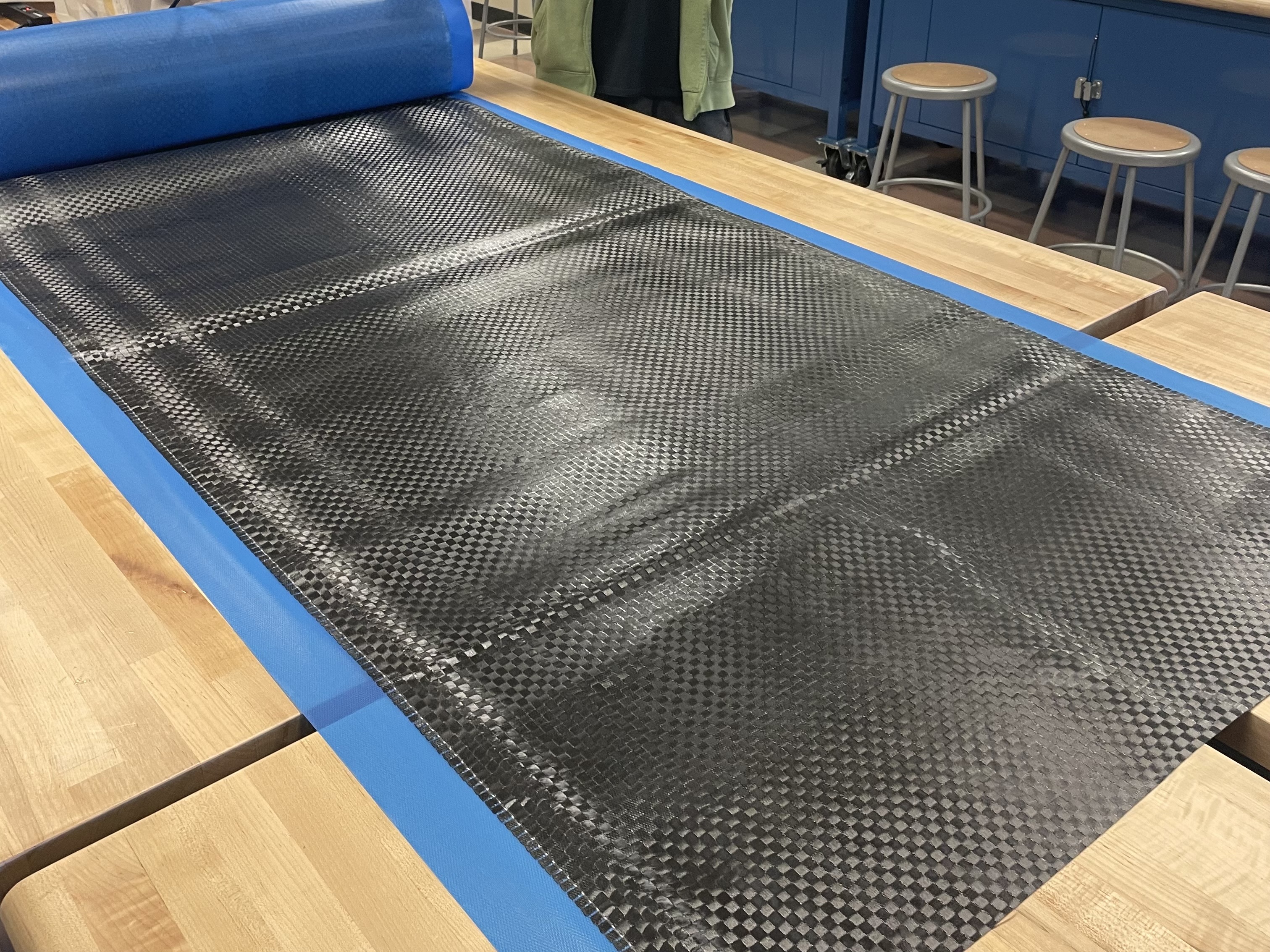
- Raw prepreg carbon fiber
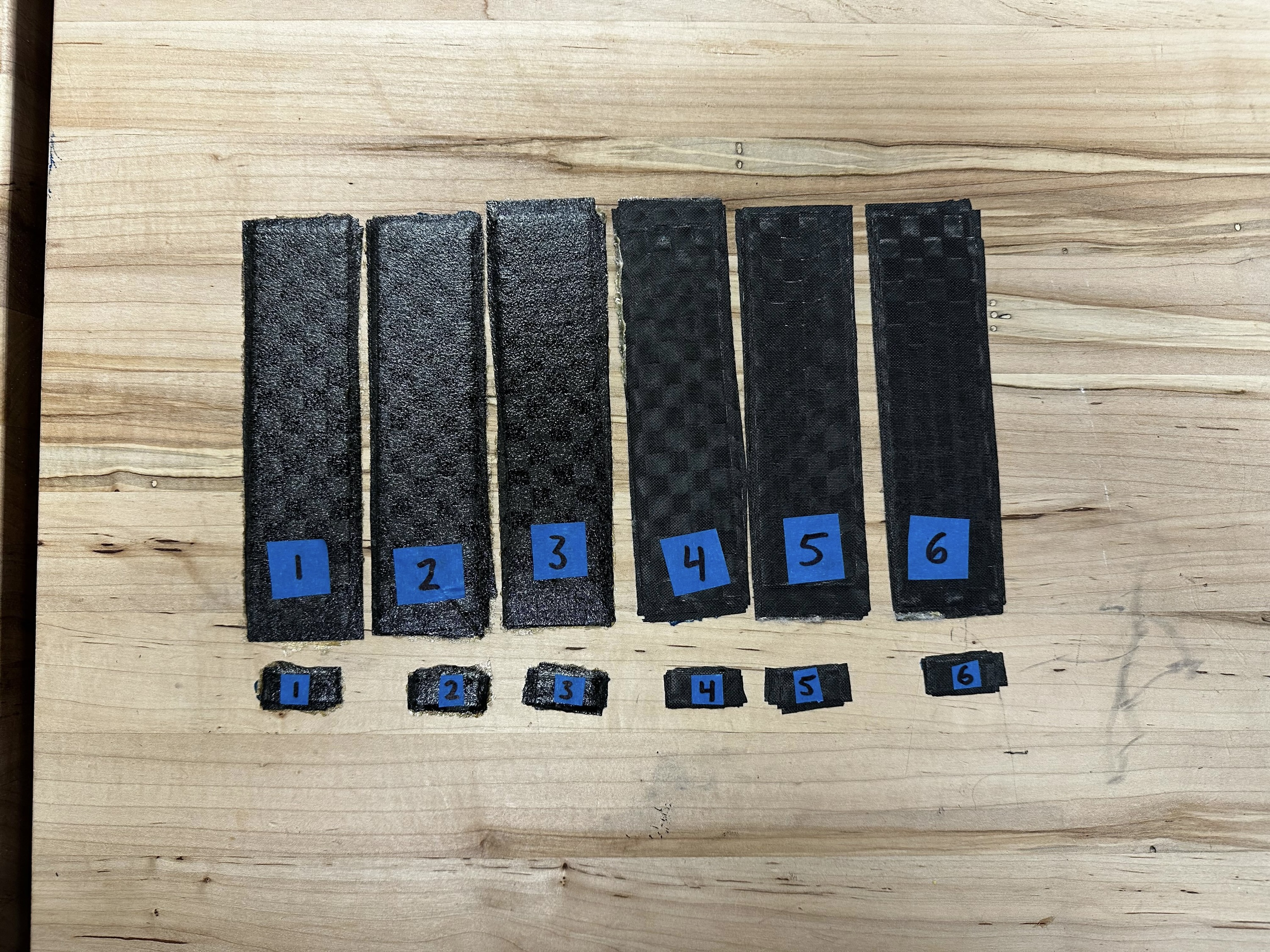
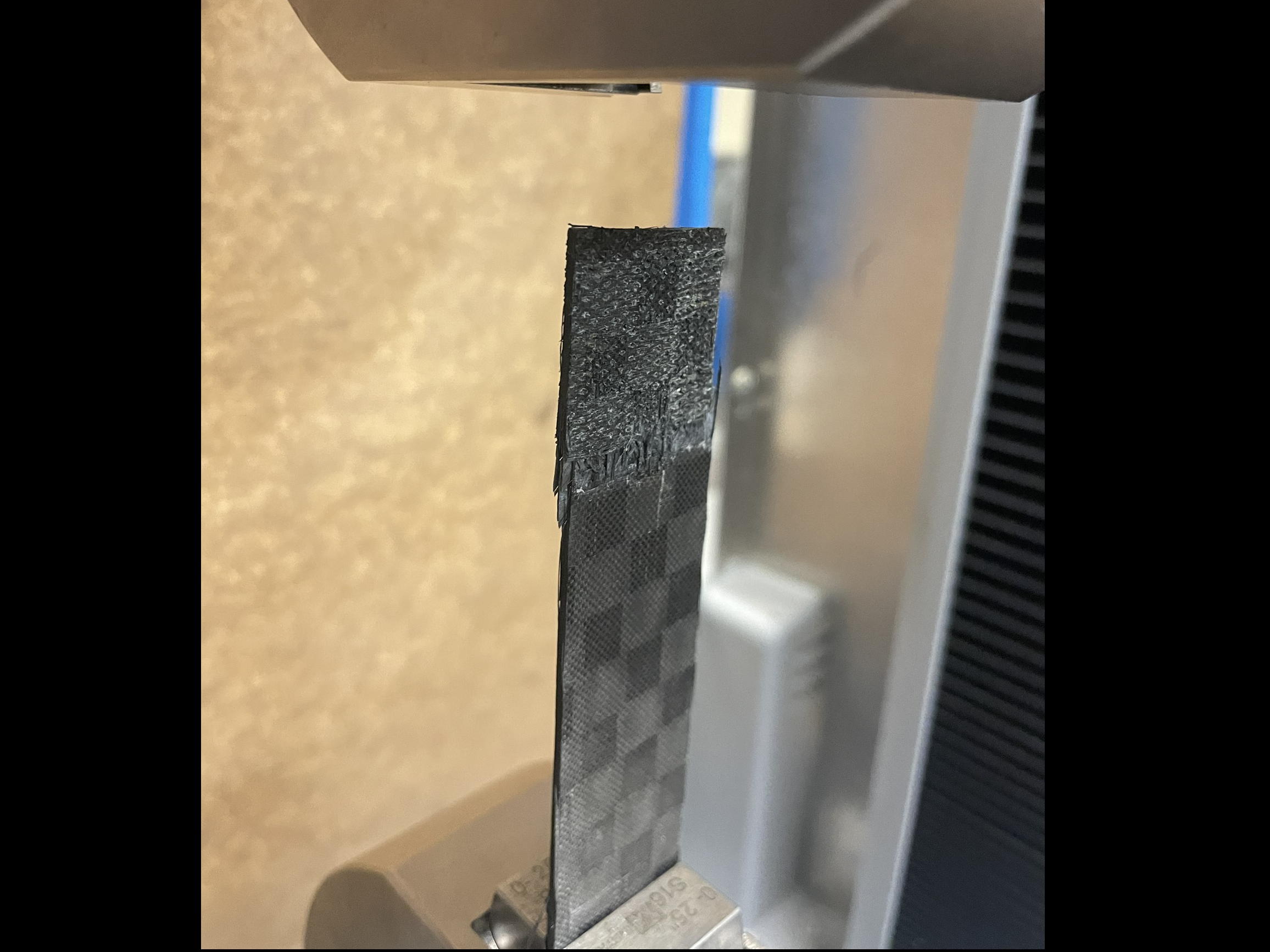
- – 12. ASTM tensile & SBS coupon manufacturing
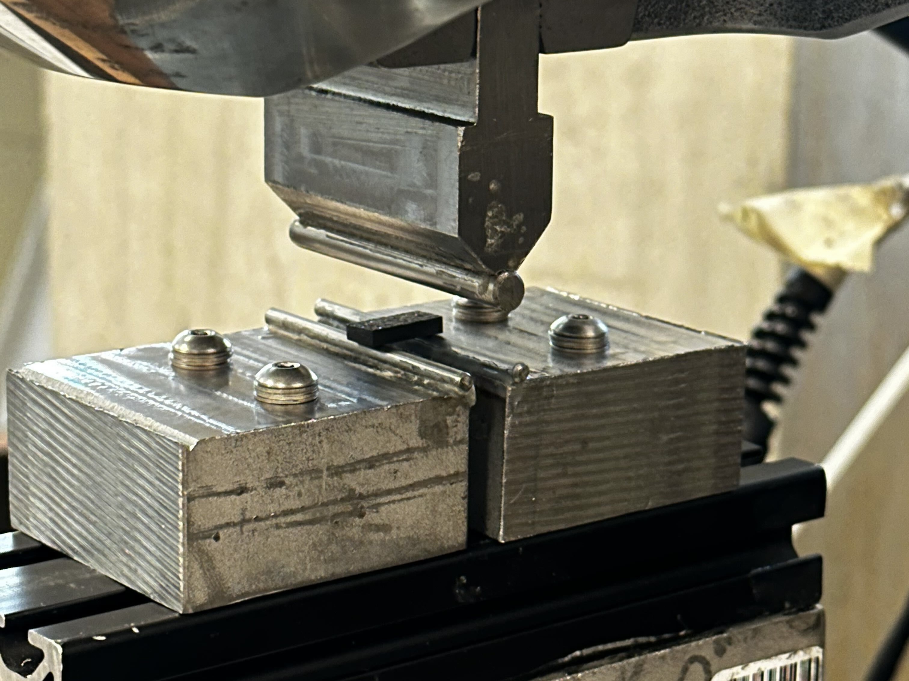
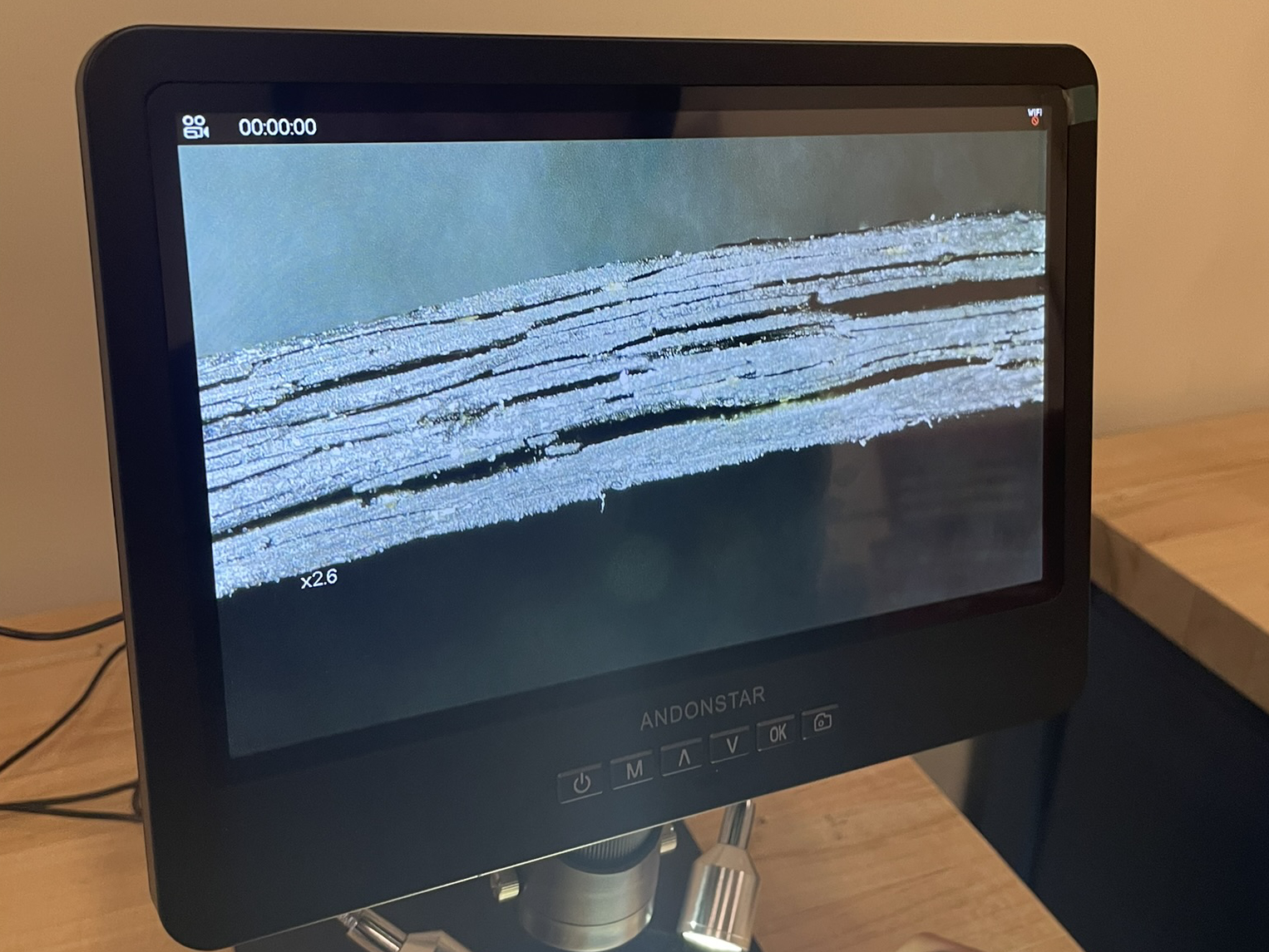
- – 15. Laminate inspection & coupon testing
Monocoque
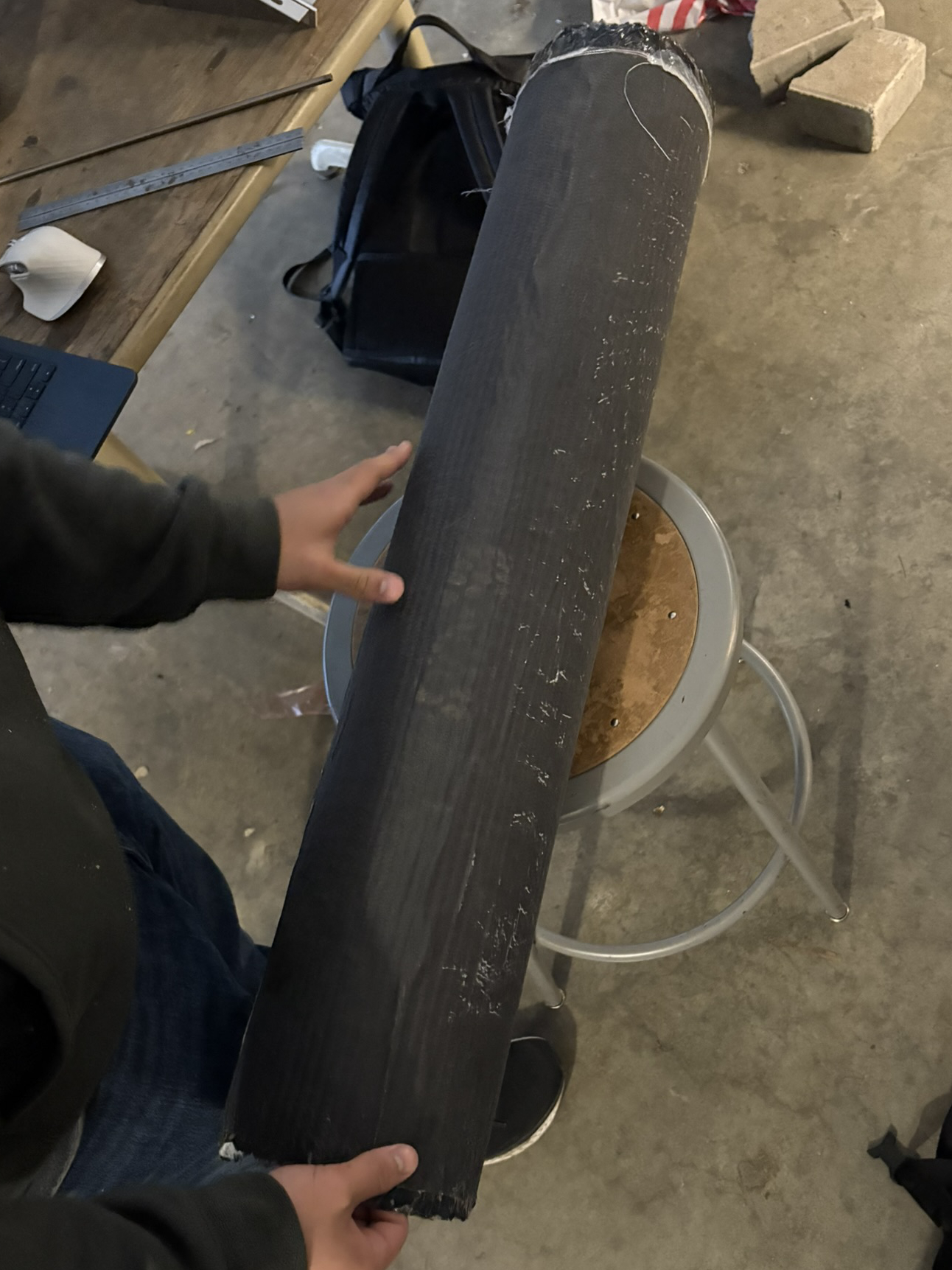
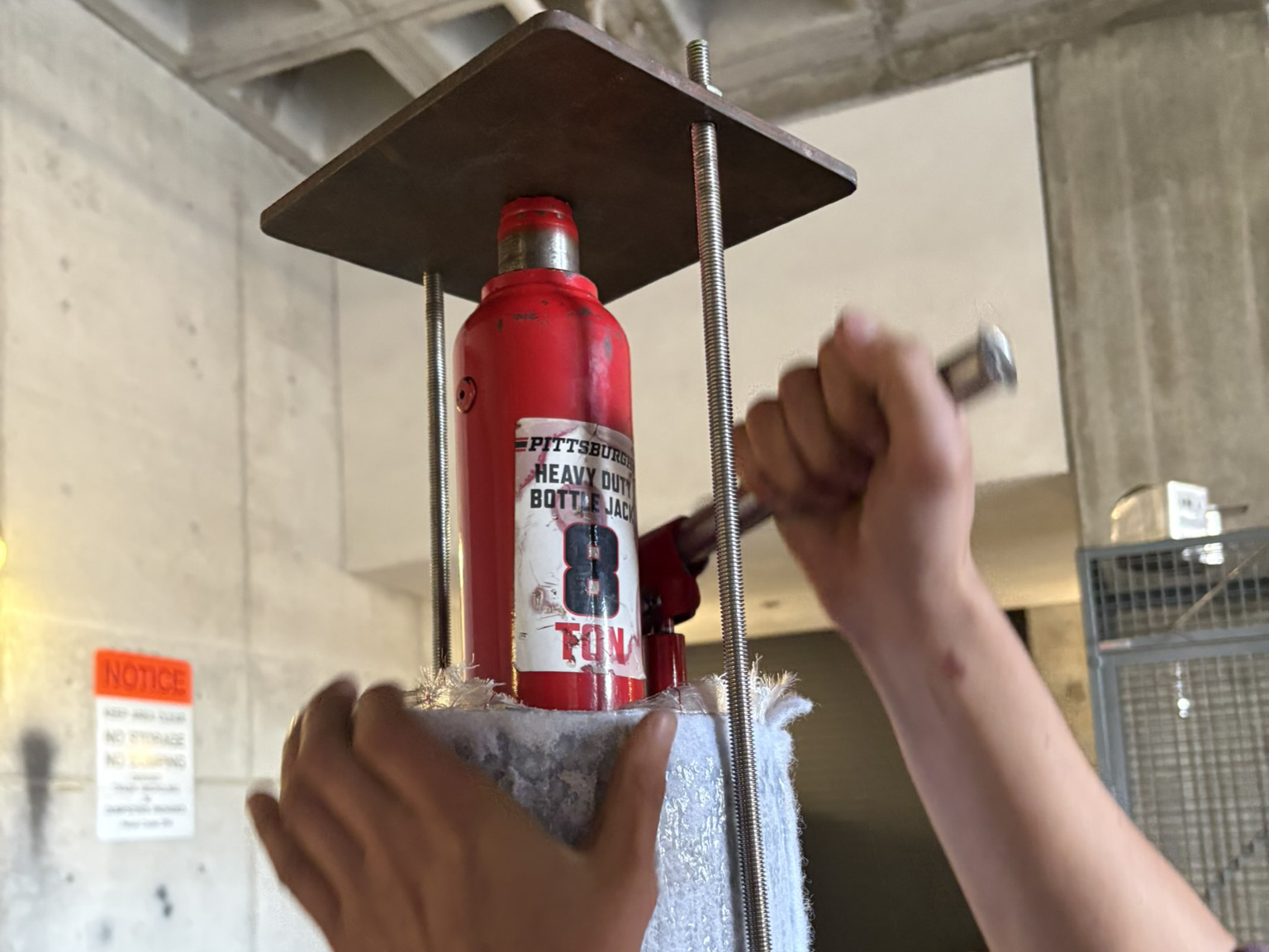
I was also the responsible engineer overseeing several monocoque layups. These components are currently a work in progress as our process develops. The process involves multiple sleeves of carbon fiber layered on a custom-sized aluminum mandrel matching the diameter of the rocket. For most successful layups, the cured monocoque slides off effortlessly, but in rare cases, or in the case of a filament-wound test monocoque, a custom-developed bottle jack rig is used to remove the monocoque. The monocoques are used to cover parts of the rocket’s outer body that the aeropanels do not. For example, as pictured, a portion of one monocoque was used for the base of the fin can (see Picture 6).
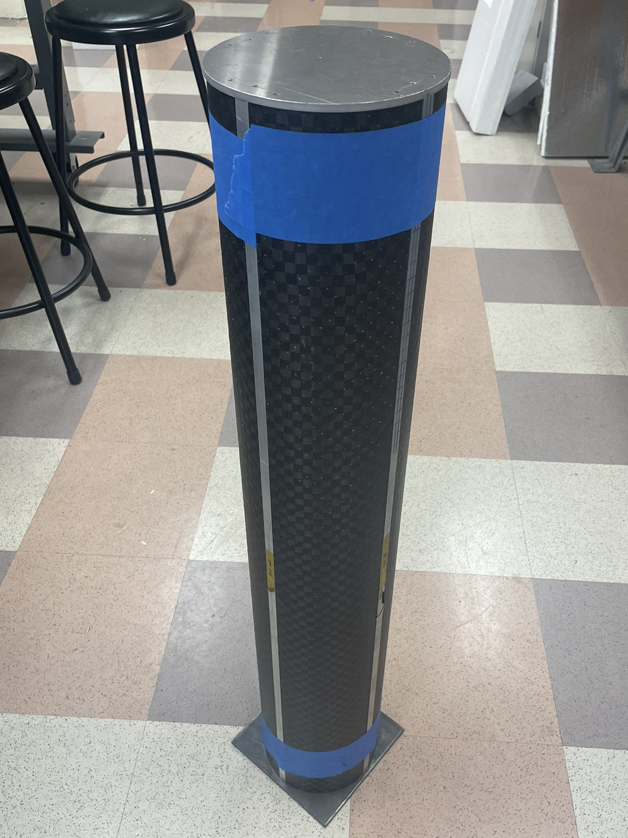
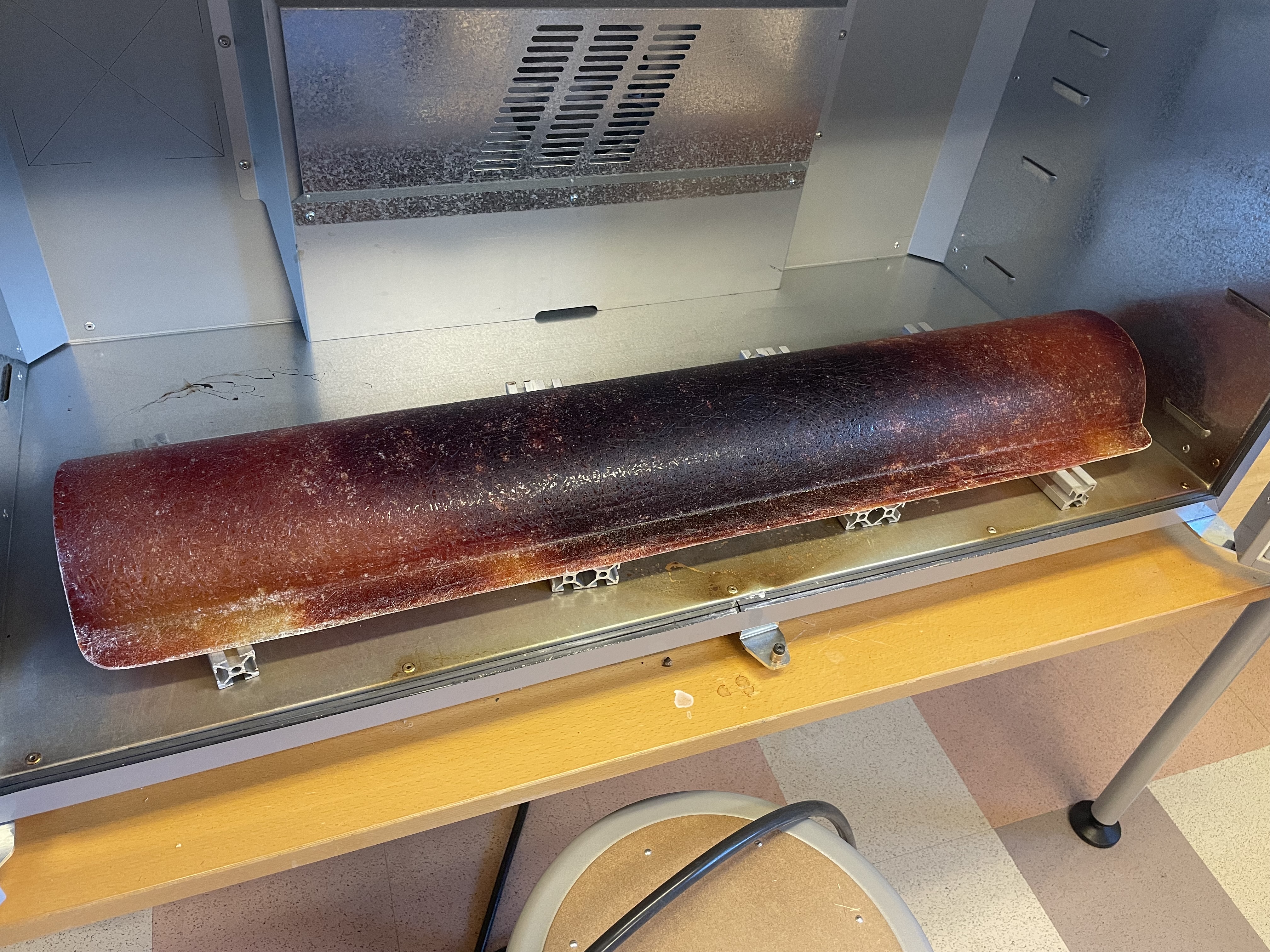
- Cured monocoque
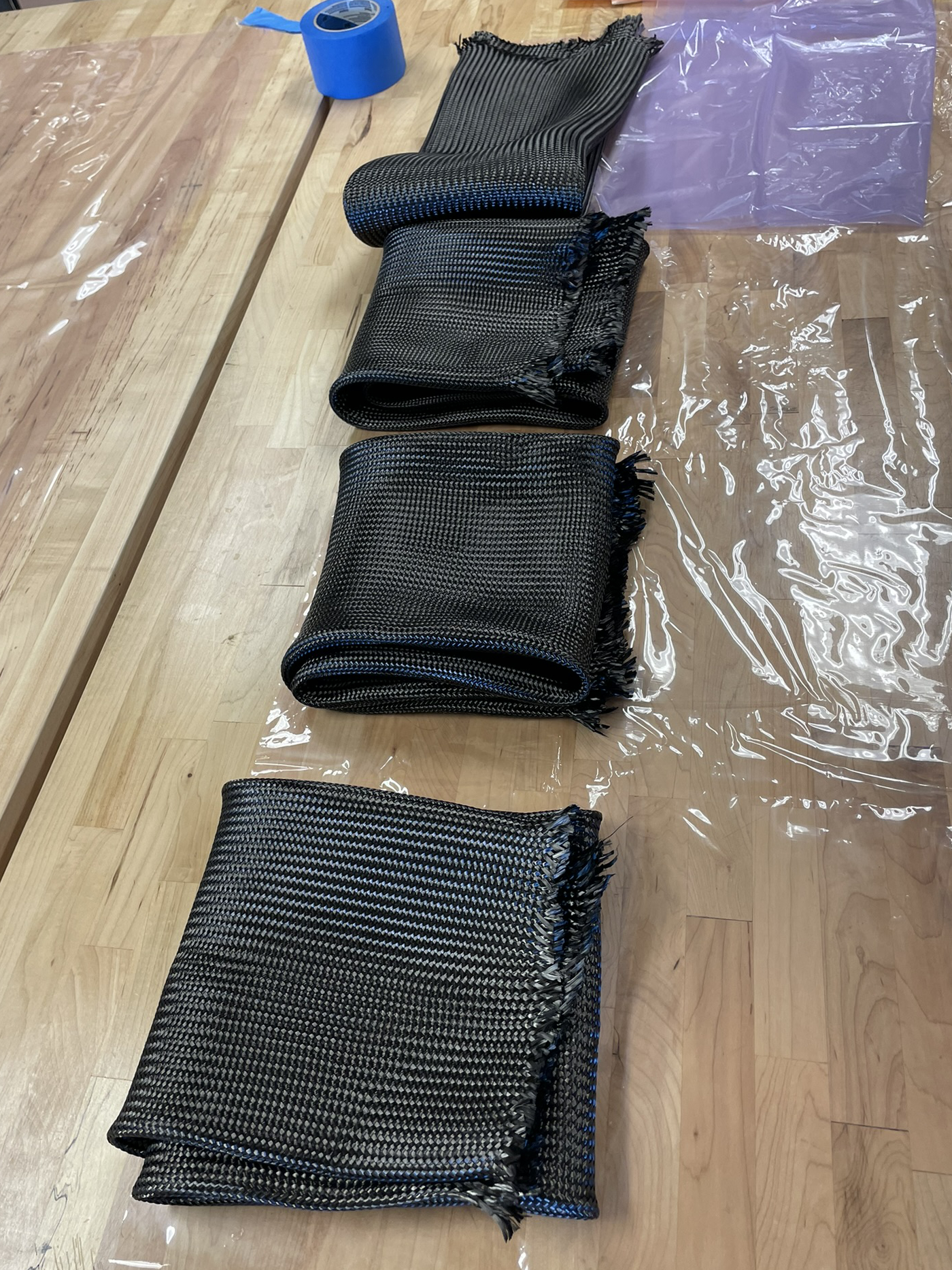
- Raw carbon fiber sleeve
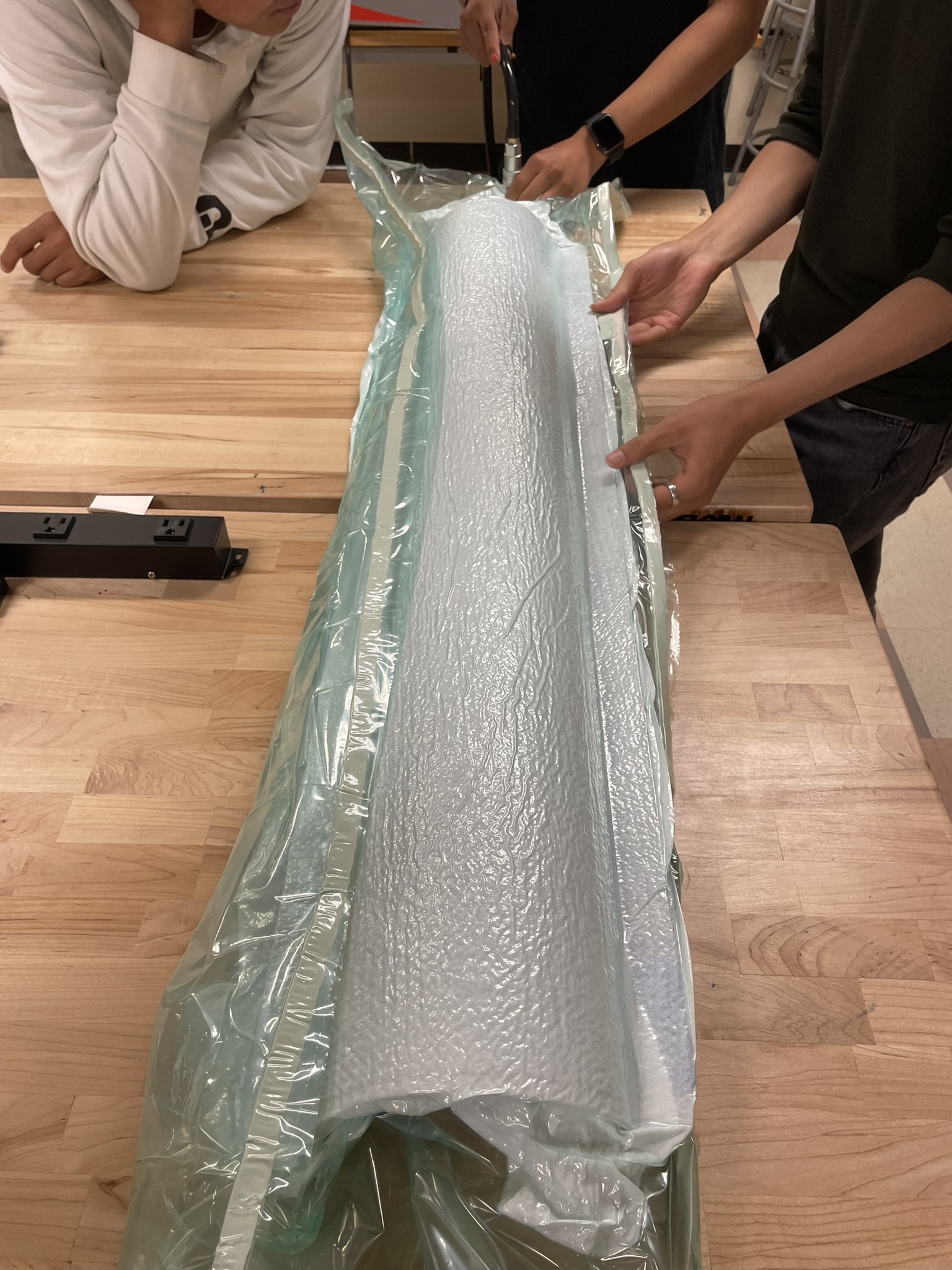
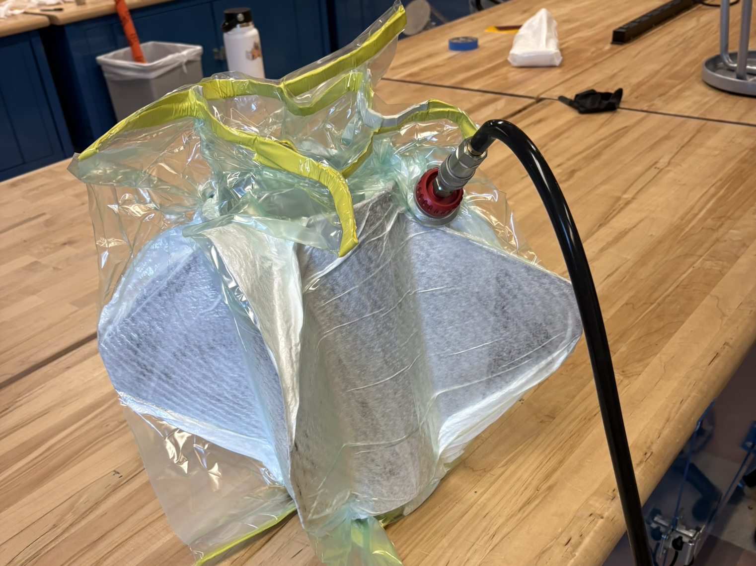
- Monocoque layup in vacuum bag, prior to cure
- Jack rig to assist in monocoque removal from mandril
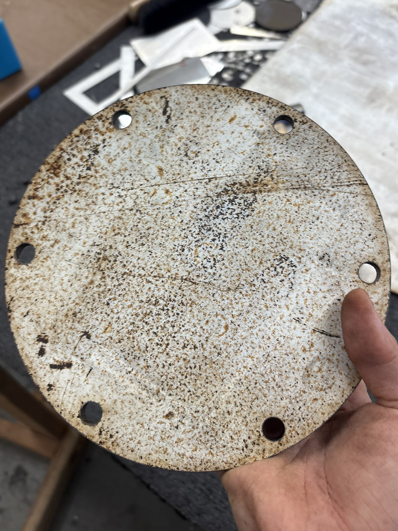
- Custom laser-cut discs for jack rig
- Fincan fiberglass layup (base was made using a portion of a completed monocoque)
Design
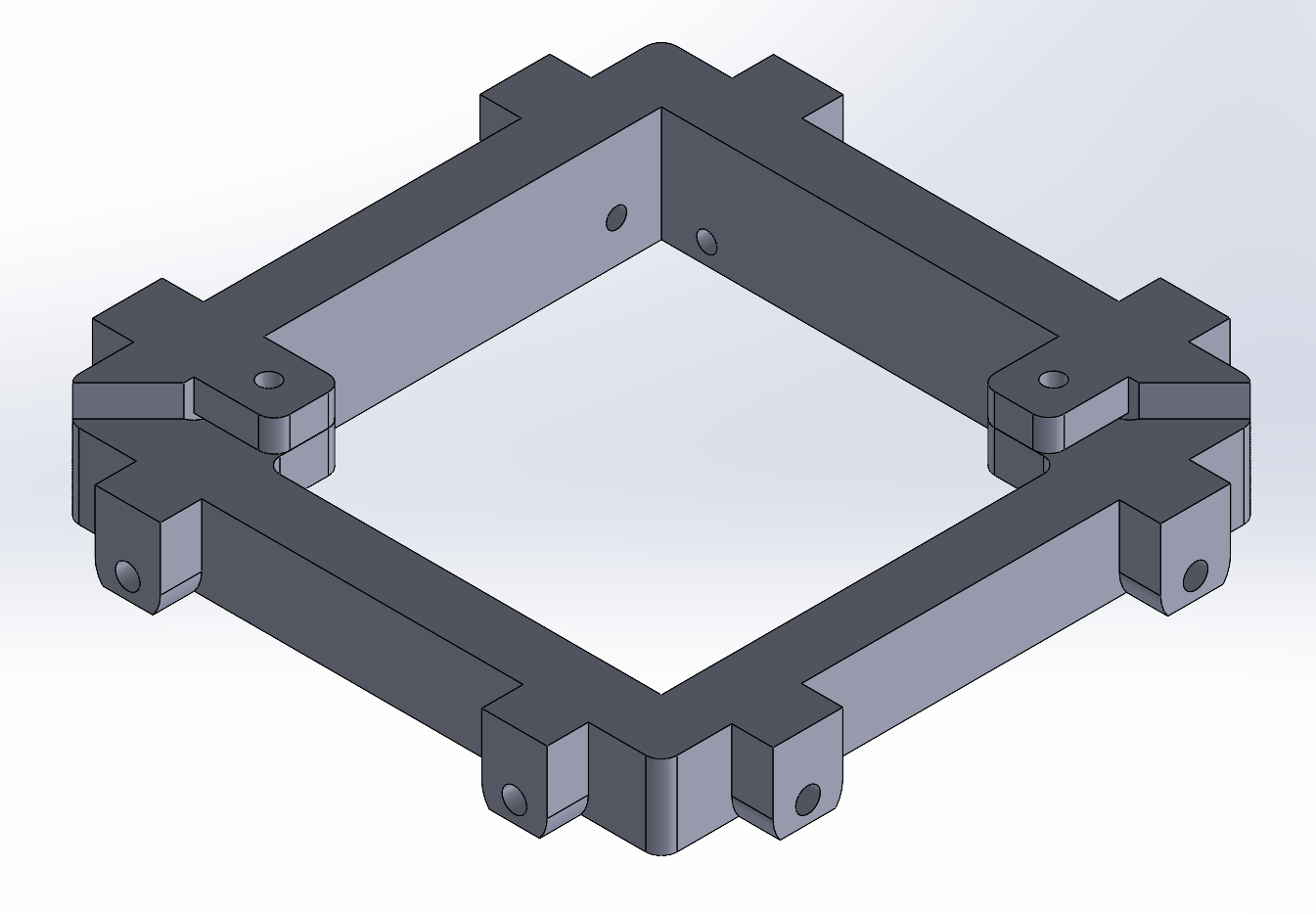
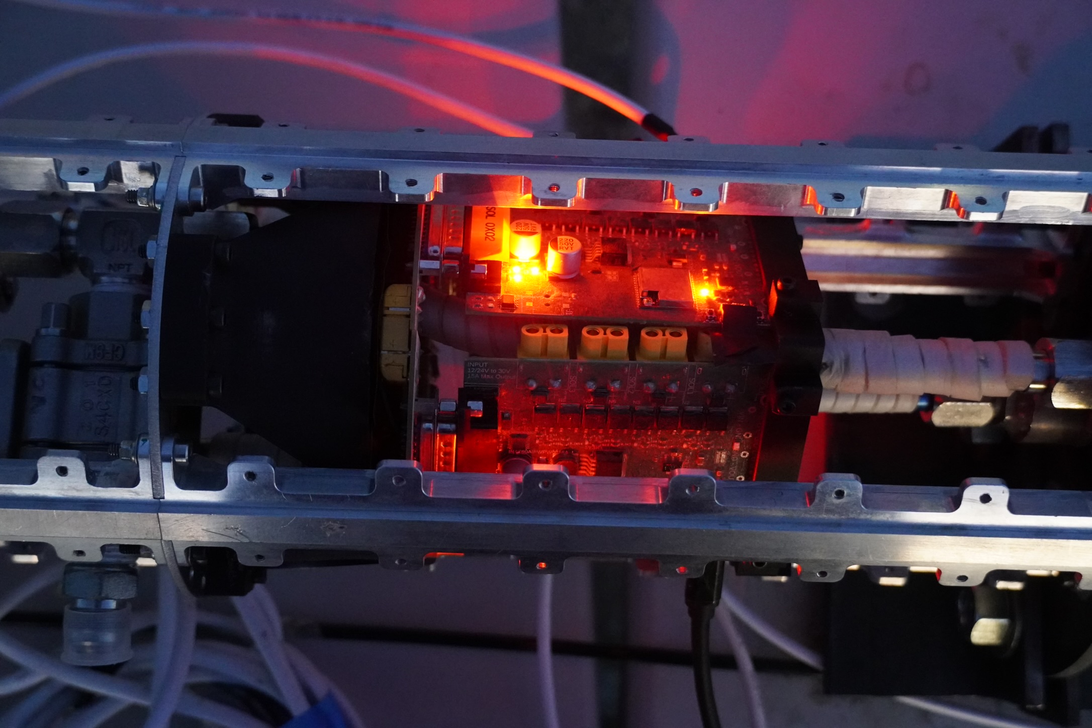
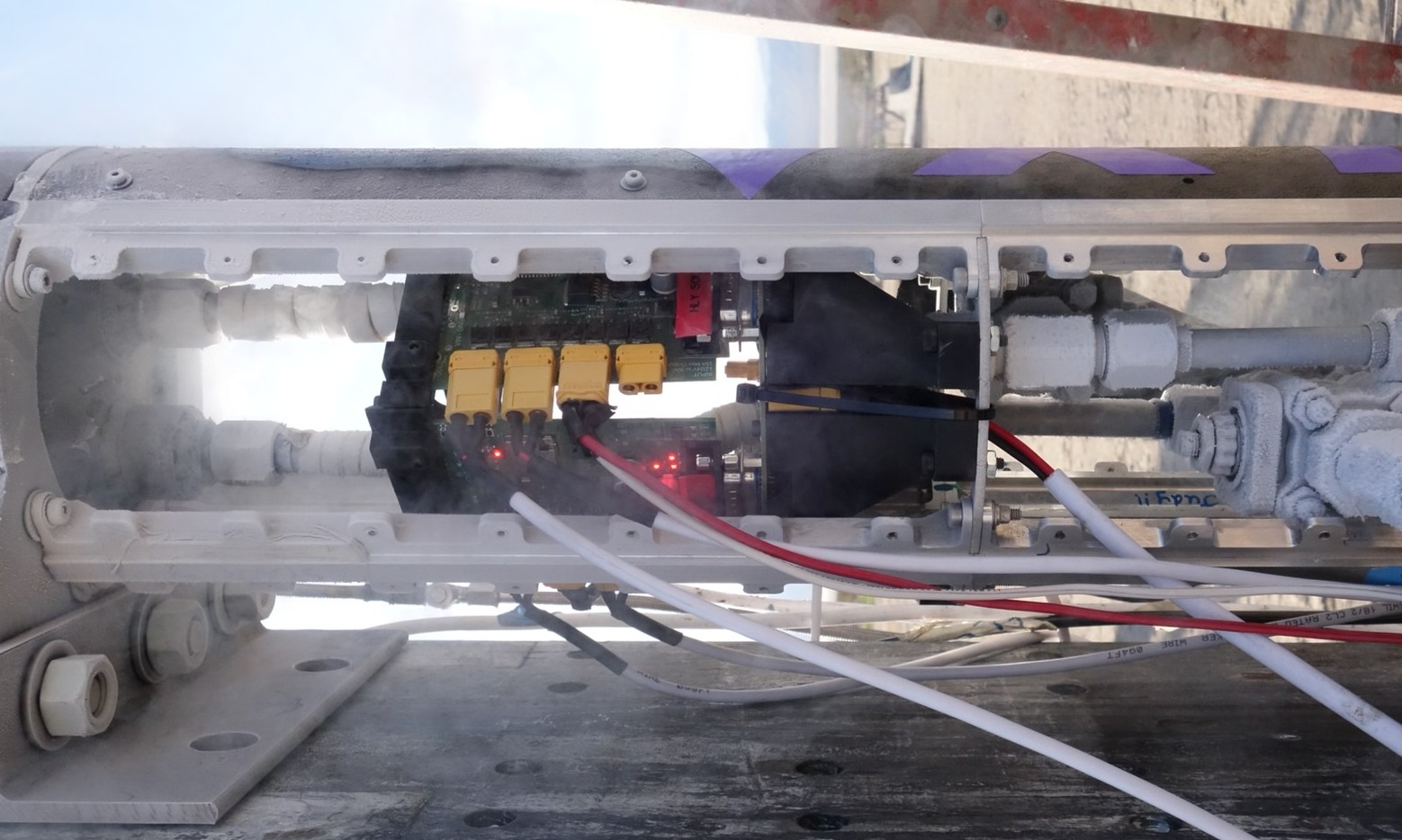
Lower Avionics Bay
The lower avionics bay is designed to fit between the struts of the rocket and around the cryogenic fuel lines. Its purpose is to secure the avionics boards against vibrational and inertial loads during flight. This part was printed using carbon fiber nylon and assembled with brass heat-set inserts to create threads.
- Isometric view of the upper component of the bay (top view)
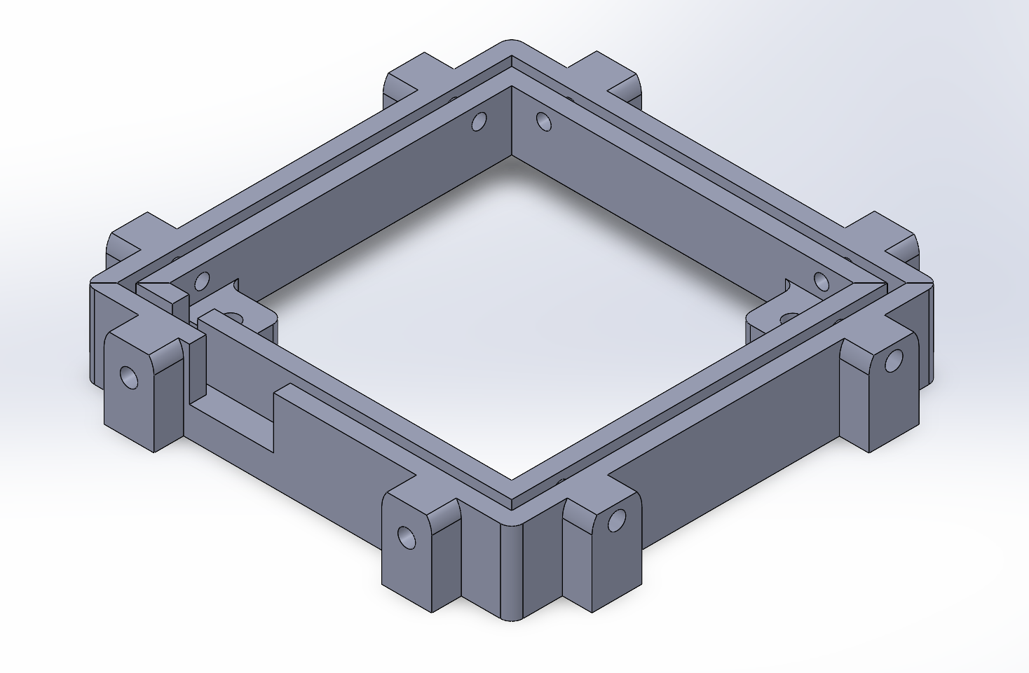
- Isometric view of the upper component of the bay (bottom view)
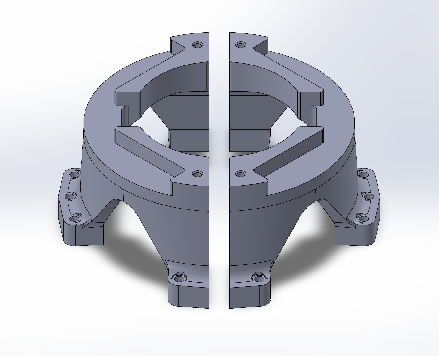
- Isometric view of the bottom component of the bay
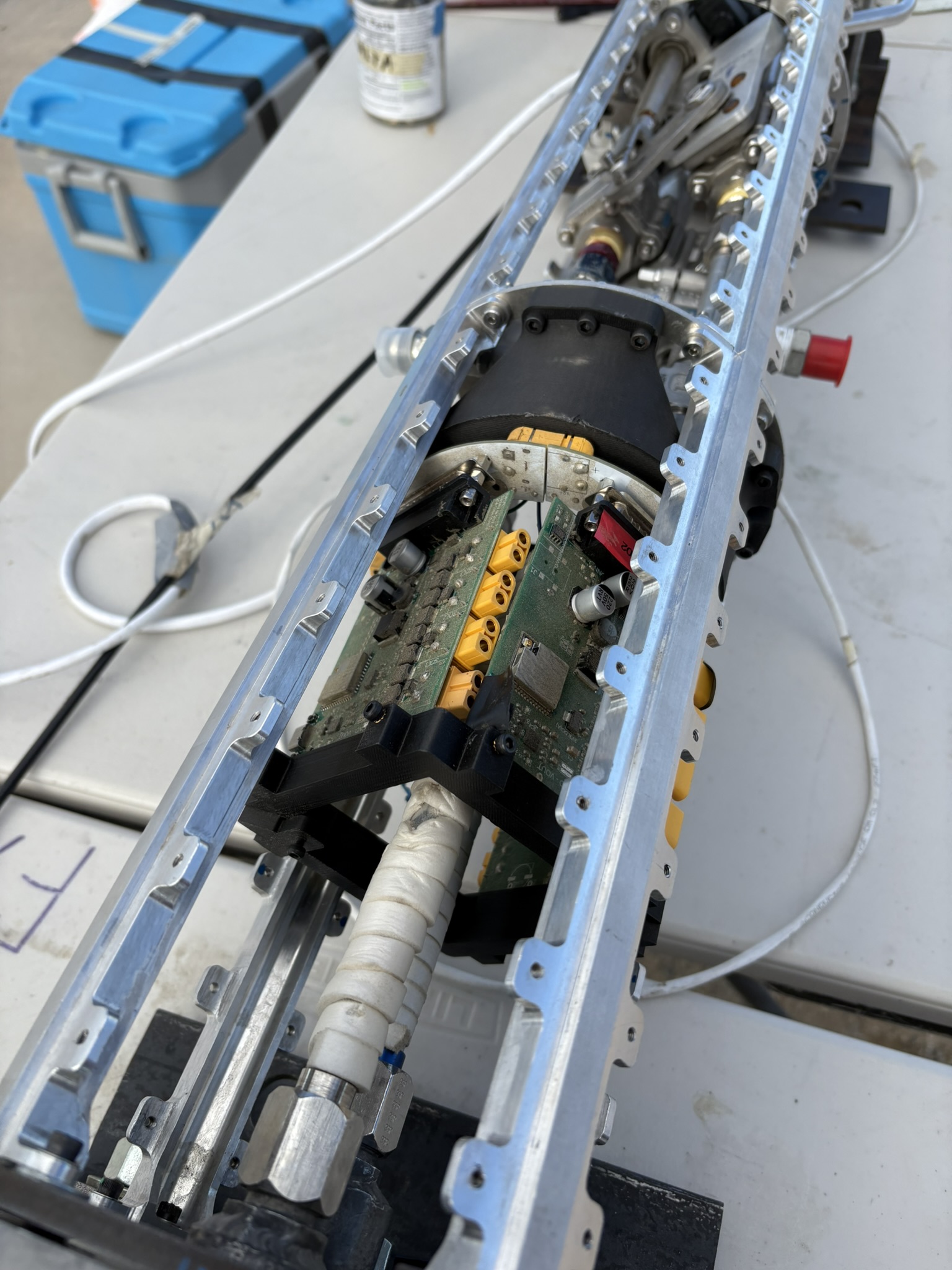
- – 6. Assembled bay on rocket w/ electronics